or, “LOL, standards” ^
TL;DR: Most motherboards have a serial header in an IDC-10 (5×2 pins) arrangement with the pins as a row of even numbered pins (2,4,6,8,X) followed by a row of odd numbered pins (1,3,5,7,9). Supermicro ones appear to have the pins in sequential order (6,7,8,9,X and then 1,2,3,4,5). As a result a standard IDC-10 to DB-9 cable will not work and you’ll need to either hack one about or buy the Supermicro one.
Update ^
A comment below kindly points out that Supermicro actually is using a standard header pinout, it’s just that it’s a competing and lesser-used standard. It’s apparently called Intel/DTK or crossover, so that may help you find a working cable.
Are we sitting comfortably? ^
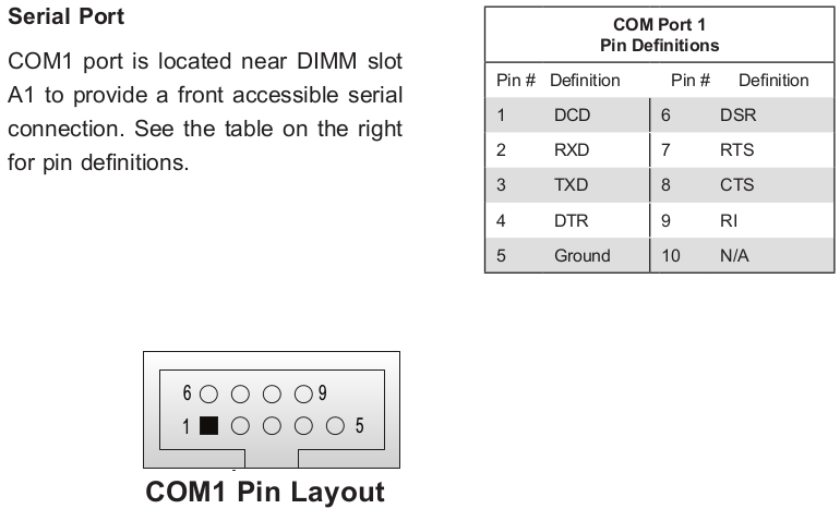
I bought a Supermicro motherboard. It doesn’t have a serial port exposed at the back. I like to use serial ports for a serial console even though I am aware that IPMI exists. IPMI on this board works okay but I like knowing I can always get to the “real” serial port as well.
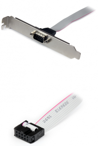
The motherboard has a COM1 serial header, and I wasn’t using the PCI expansion slot on the back of the chassis, so I decided to put a serial port there. I bought a typical IDC-10 / DB-9 cable and plate:
Didn’t work. Serial-over-LAN (IPMI) worked alright. On COM1 I would get either nothing or a run of garbage characters from time to time. I wasted a good number of hours messing with BIOS settings, baud rates, checking if my USB serial adaptor actually worked with another device (of which I only have one in my home), before I decided to sit down and check the pin numbering for both the header and the cable.
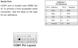
Looking at the motherboard manual we see this:
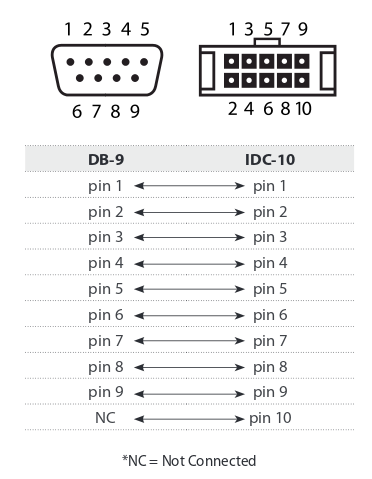
And the cable?
Notice anything amiss?
The cable’s pins go in a row of odd numbers and then a row of even numbers:
2 4 6 8 X
1 3 5 7 9
    -
The X is the missing pin (serial uses 9 pins) and the - indicates where the notch for the connector would be: next to pin 5 in this case.
The header’s pins go in sequential order:
6 7 8 9 X
1 2 3 4 5
    -
As a result all but pin 1 are incorrect.
You actually need a Supermicro cable for this. CBL-0010L is the part number in my case. CBL-0010LP would be the low profile version. Good luck finding it mentioned on Supermicro’s site, but your favourite reseller will probably know of it. As it was I found one on Ebay for £1.58+VAT, and it works now.
After knowing what to search for I also found someone else having a similar issue with a Supermicro board.
You could of course instead hack any existing cable’s pins about or fit an adaptor in between (as the person in the above link did).
Thanks Supermicro. Thupermicro.